|
| Its been awhile since I've been on SourceForge. But I've been working on some new things that I will probably put up here soon. Also I now have a flickr page with lots of my photos.
|
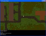
| Go download the new JavaUOClient-.50, it now has a graphical client using map0.mul and radarcol.mul which must be added to the folder it is ran from. The new version uses these to draw a grid of 8x8 blocks of cells whos color is defined in radarcol. This means it will look like a real basic UO without statics, for an example look at UOAM with hidestatics on.
  
|
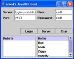
| There is a new version of the windowed java UO client, JavaUOClient-.40 is up and working fine, so go and try it out. I have also been working on reading the graphics files from UO so I hope to have a release up soon with some actual graphics.
|
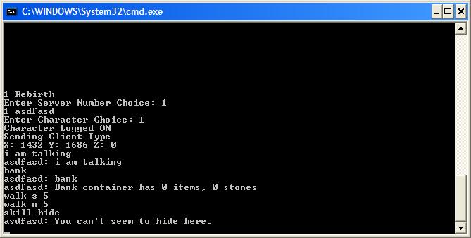
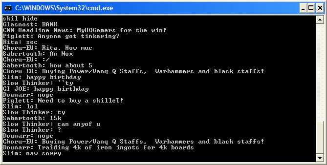
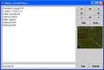
| ConsoleJavaUOClient-.30 has been released! I completely rewrote all the networking code and fixed all the bugs I knew about. It now runs and works better than before on all systems I have tested it on including Windows XP, Gentoo Linux, Unix, and Debian Linux running on a Sparc. The new code has only been added to the console version for now, but will soon be added to the other JavaUOClient-.40 release soon (thats the GUI version). For now though go download here.
|
| I have released a java http proxy. It is very simple but it works. The newest version, version .3, uses multiple threads to handle connections. Download it here.
|
 |